


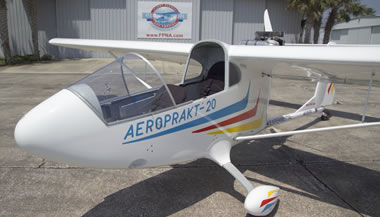
Getting the Ukraine Plaine I wanted,
An Aeroprakt A26 to A20 conversion
Imagine having a light plane designed by a design team from Boeing or Douglas. Do you think it would be a pretty decent design? Well… how about a plane designed by a team from Antonov Design Bureau? That’s the group that designed and built USSR commercial airliners and cargo planes, and even the worlds largest cargo plane. If you find bush planes interesting, look up the Antonov AN-2, the first plane from Antonov in 1946.
In 1991, in the Ukraine, several engineers, from the Antonov Design Bureau in Kiev, got together and started a company making UL kits and then later LSA’s and light twins. They continued to work for Antonov for a few more years, working their little company after hours and whenever they could.
There are more planes flying in the world with the Antonov name plate than any other brand. These fugitives from Antonov called their company Aeroprakt, which is copied from their previous flying club, Aeropract, and their UL designs were arguably the best ever. They are now making LSA’s and other specialized planes being sold the world over. Their early UL’s have won the UL flying championships in Europe many times. And when they say UL, that is Ultra Light by European standards, which was pretty much equivalent to our current LSA here in the US.
Their first product was a single engine pusher, the A20 Kit, in 1992, . There are many of these planes in Eastern Europe.
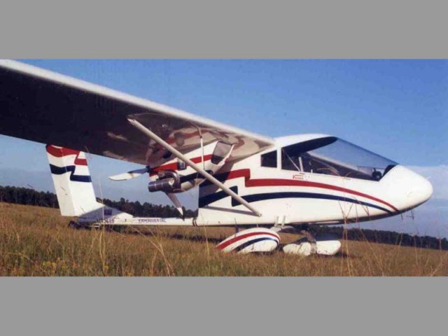
This is my story of taking their twin engine kit, the A26, and converting to a single engine configuration. This is possible to do, because the twin engine version was an adaptation of the single engine version.
The A20, the single engine kitplane, was sold with several different wings, 28′, 31′, 33′, and 38′ wingspan. For the twin version of the kit, both the fuse and the wing were made beefier and a couple of Rotax 582 two stroke engines were hung on the trailing edge of the 38′ wing.
Both are pushers, the twin with dual Rotax 582’s and the single available with several different engines, with the most popular in the US being the Rotax 912. The fuselage is very similar, with beefed up bulkheads for the twin where the front and rear spars attach. It appears that both fuselages came from the same basic mold. The A20 was sold in Europe for almost 10 years before it came to the US.
The most outstanding feature of the A26 was it’s climb ability. The spec was 2700 fpm at full gross, an amazing elevator ride, and into fighter plane performance territory. Similar to the Aircam, and probably a bunch lighter in weight. The worst feature of the Twin, at least in my opinion, was that it had two Rotax 582, two stroke engines, each burning about 5-6 gph, for a total of 10-12 gph. That’s a healthy appetite, and since I like to fly a lot, would be just too expensive for me. A20 owners with the 912 claim to burn about 4.5 gph at cruise.
The A20 with a 912 would not climb nearly as well, only 1500-1700 fpm, (still pretty good) but actually went faster, with a faster cruise. The A20 with 38′ wing and all the fairings has a glide ratio approaching 18:1 and will thermal and soar very readily. This is what attracts me to the plane and to the long wing in particular. I soared a lot in my Challenger 2, with a 10:1 glide ratio. You could really core a thermal, cause it was so slow, but not do very well getting to the next one. Still it was a lot of fun. This plane should be even better.
Other differences between the two– The A20 came with wing tanks, the A26 did not, probably because of the beefier structure needed to carry those two engines. The A26 also had a larger tail, both vertical and horizontal, and a huge rudder. I don’t mind that at all, cause, as my instructor friend Randy says, you can never have too much rudder. :o)
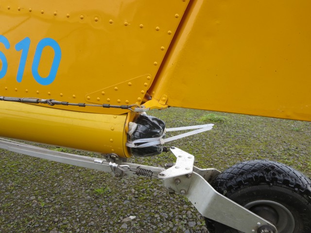
The A26 also had a beefier landing gear, and bigger tires, with large wheel pants that are just beautiful on this plane. The gross was also a little higher, 1126 lb vs. 1050 on the A20.
There was also an oddity with the landing gear on the A26. It was tilted back by 12 degrees, in order to move the wheels back a couple inches. I don’t know why for sure, everyone I’ve talked to seems to have a different opinion. It may have had to do with CG, or tail wheel weight, or both. The factory isn’t saying. In any case, I think it was this odd mounting of the gear increased the torque loading at the gear mounting point and may have made the fuselage more susceptible to damage.
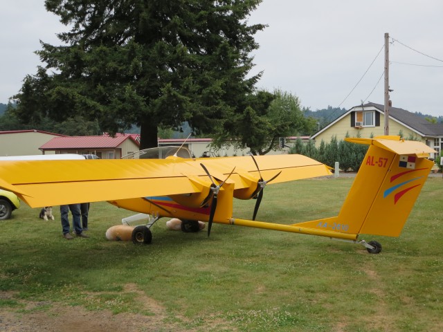
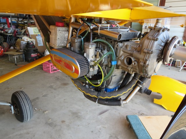
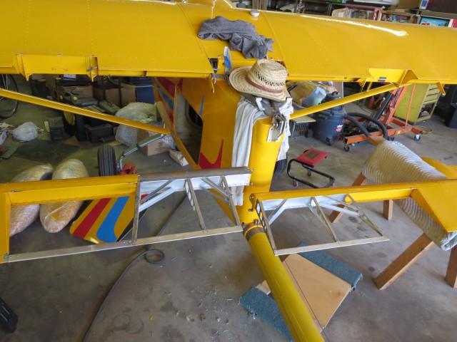
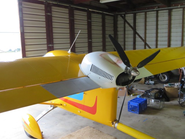
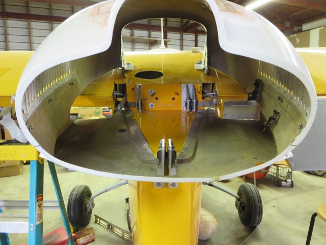
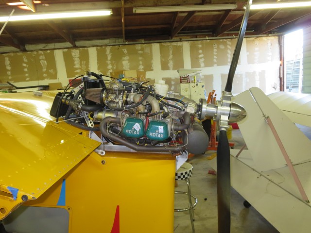
Here’s a picture of the converted plane very near completion. All that remains is to paint the added and modified bits, such as the motor cowling, ailerons, and so on.
History
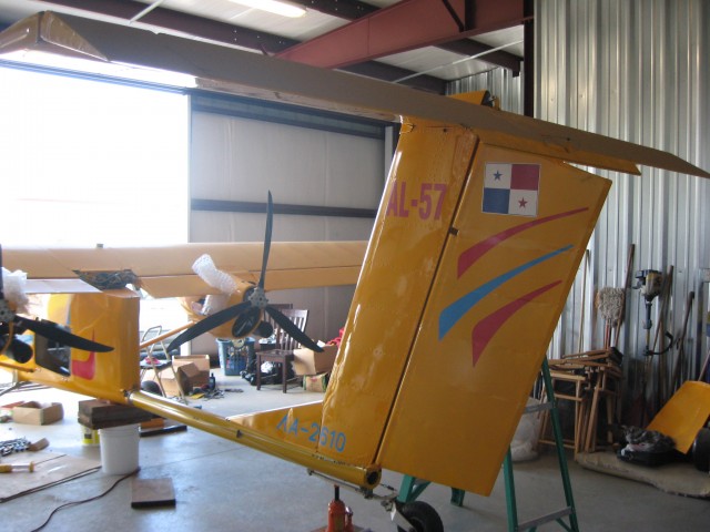
This kit, complete with two 582’s, was originally purchased through the US importer, Spectrum Aircraft, and delivered to a flying club in Panama, in December of 2001. In February of 2004, it was registered in Panama as an Ultralight or “Ultralivianos”, with tail number AL-57.
Sometime in the late 2000’s, the plane was subject to a crash landing that damaged the fuselage on the right side, and put a twist in the tail boom. I imagine the right wheel hit a hole or depression and was twisted backward, bulging out the fiberglass on the back side. The fuse did not collapse, but was terminally damaged. A makeshift repair was done to the fuse on the inside. The plane then was bought by the 2nd owner, an American, who was a good friend of the first owner. He put it in a shipping container and brought it to Sandy, Oregon in 2010.
I heard about the plane through the grapevine, and went to see it in November, 2011. At that time the owner was not interested in selling. He had just made a new tail boom part, and replaced it himself. No work was yet done on the fuse pod.
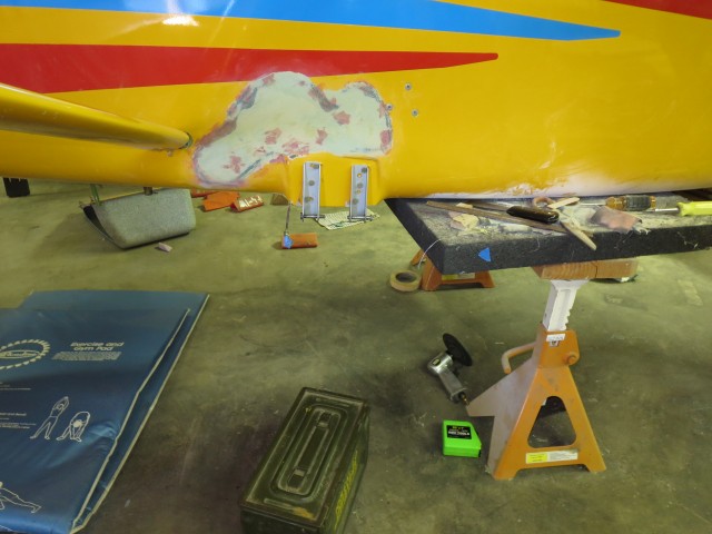
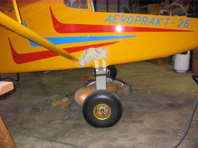
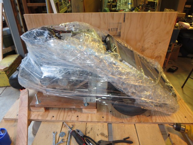
I bought the plane on July 29th of this year (2013) when the owner was moving to the Philippines. In my hanger, you can see that the crack and bulging of the fiberglass has gotten progressively worse. In my opinion, especially after having now done the repair, it was just a matter of time until it collapsed, which would have totaled the airplane if it was landing or taking off at the time. Here’s what it looked like in August of 2013.
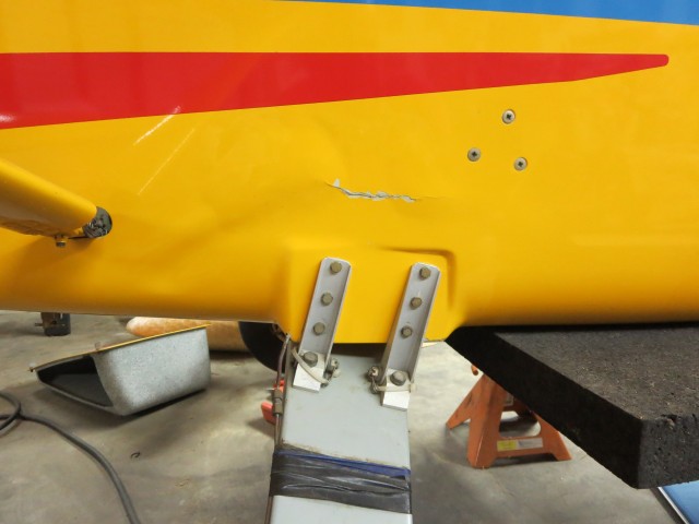
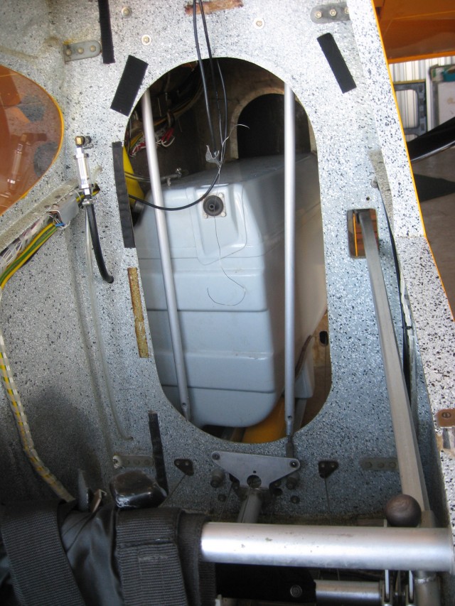
There is no superstructure on the inside of the fuse, attached to the landing gear. The gear is mounted to an aluminum plate and the plate is glassed into the fuse. The fuse is made from foam core construction, and is very strong, but it needed to be repaired properly.
My plan was specifically to convert it to single engine configuration, with a Rotax 912 engine. I knew it was going to be a lot of work, but I really wanted one of these, ever since I first read about the A20 in Ultralight Flying magazine way back in 2001, when I was building my first plane, a Challenger 2. Aeroprakt stopped all production on the A20/26 kit in 2004. There are about 12 of the A20’s left in the US, and about 7 of the twin engine A26. The factory now makes completely finished LSA and light twin aircraft and has become very successful, worldwide.
I suspected that the plane was still registered in Panama. My god-daughter who is fluent in Spanish, spent an afternoon with me talking on the phone to Panama. It was, and we did get it de-registered.
There is only one 38′ wing A20, with the 912 engine, in the USA. It is in Durango, Co. The owner is not interested in selling. I figured this damaged A26 twin was going to be my only shot at getting what I wanted. It turned out to be even more work than I thought, but… if you’ve built a plane, you know… it’s always that way.
In an additional stroke of luck, I guess you could call it that for me, but not the owner, I was able to get some crucial parts from a single engine A20 that had been crashed in the Portland area. Sad, because I knew the owner/pilot, but at least he wasn’t hurt in the crash. I got a motor mount, and several fiberglass pieces, most importantly, the engine cowling, AND, the engine, prop, and associated pieces such as the radiator, oil cooler, other bits, and even the EIS that had been with that motor since it was new. The EIS still had total engine hours on it.
So, really, my plan was to take one crashed plane, and parts from another crashed one, to make the plane that I had wanted for so long. This was my chance to have one of these Ukraine Plaines, and certainly the only way I could afford one of them.
There would be several parts to this project:
1. Repair the damage to the fuse or buy a new one from the factory in Ukraine.
2. Mounting the landing gear correctly, or straight, on the fuse. The same way it is mounted on the A20. I think that the damage in the crash landing was partially caused by the tilted back mounting, which imparts more of a torquing load on the fuse, especially if a tire hits a hole or obstacle when landing.
3. Removal of the two engines from the wings and remove all associated wiring, controls and fuel lines.
4. Mounting of the 912 on the rear of the fuse. Then hook everything up. I knew this would be the biggest challenge and in fact, it took almost half the building time.
5. Repair the cowling which was cracked from the crash and had been partially cut up, and mount it on the plane with Dzus fasteners. Repair the other fairing pieces which were damaged in the crash.
6. Rewire for the single engine and make appropriate changes to the panel.
7. Rebuild the Ailerons, filling in the space where the motors were, and fill in the gap in the wing upper surface.
8. Add weight or move components as required to achieve a good weight and balance.
9. Get the instruments working. The radio, transponder and attitude gyro were non op when I acquired the plane. This turned out to be a lot more effort than I thought.
I’ll go over these one at a time, even though the building process proceeded with a lot of overlap. I often had 3 or more of these projects going at the same time.
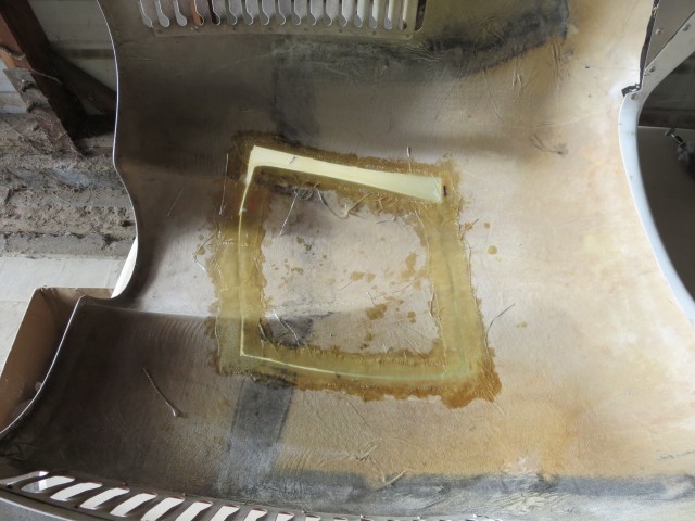
Fuse repair and remount gear
First, the tail boom had already been repaired by the prev owner. The fuel tank had to be removed and access to the boom was from the front, through the passenger compartment, and from the side, through the access panel.
I’ve worked with fiberglass a bit, enough to know my way around a brush and a cup of epoxy. I had never repaired a foam core part before, so this was definitely out of my knowledge/experience range. I had to find someone who knew what to do. Turned out, I had an email acquaintance with a very accomplished glass guy who had the same kind of plane as my other homebuilt, a little Mini Max all wood plane. He made and sold various parts for that plane, like an engine cowl, wheel pants, etc. both from glass and carbon fiber. This was a sideline for him, he made his living flying around the country repairing composite planes such as Lance Airs, Long EZ’s, etc. that had been damaged. He really knew his stuff. I had bought an engine shroud and drooped wingtips for my other plane from him.
And as always, he was willing to help. I sent him pictures and he told me all about how to do the repair. First I cut back all the bulged out glass on the outside of the fuse. Inside, I found a crushed foam core and poorly done core reconstruction done from the inside of the fuse. What was necessary was to reconstruct the core, and once that was done, then simply repair the outside glasswork. I also ended up adding a few cloth layers to the inside. It turned out to not be that difficult, but was very time consuming.
I also found on Youtube, several videos showing how to repair damaged foam core construction. The internet is an incredible resource.
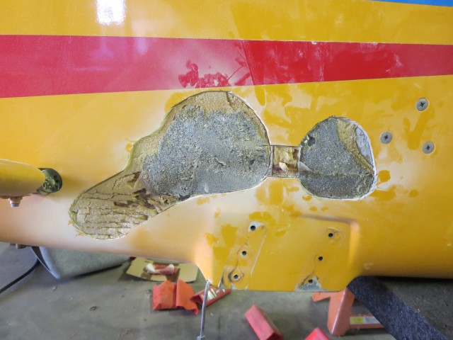
I had to grind away a lot of the previously replaced core to take the bulge out of it, and remove the crushed foam. Reconstructing the foam core could be done with most any material that had the right kind of strength. I ended up using plywood layers, epoxied together and the existing epoxy from the previous repair.
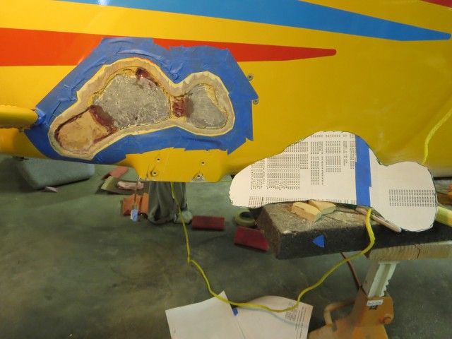
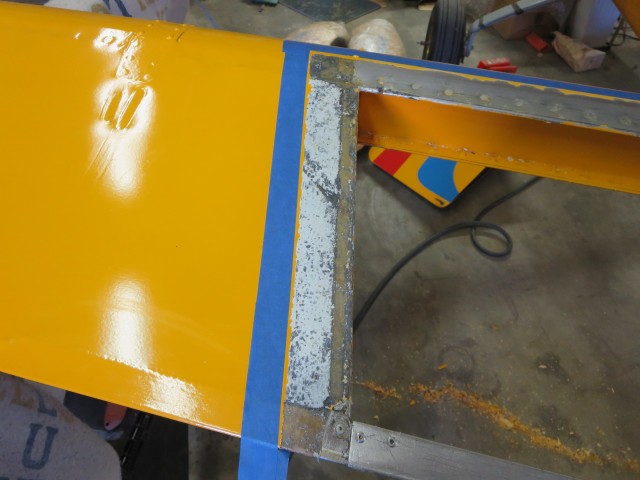
In the picture you can see one of the patterns I made for cutting out the glass cloth pieces to be layered over the core, with the edges just touching the beveled edges of the existing glass on the fuse. This I knew how to do.
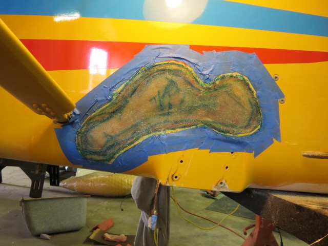

The only part that was not to turn out well on this repair, was the surface level in relation to the fuse. The edges of my glass work ended up being higher than the surrounding fuse, which will show up in the paint. I hesitate to sand it down to be level, because that would sand some of the glass cloth away, right where it joins the old structure, and reduce the strength of the glass repair. I can smooth it as best I can with bondo, and it will be partially covered with a fairing that streamlines the gear to fuse joint, so it will not be too noticeable. This is the price I pay for not being an expert at this.
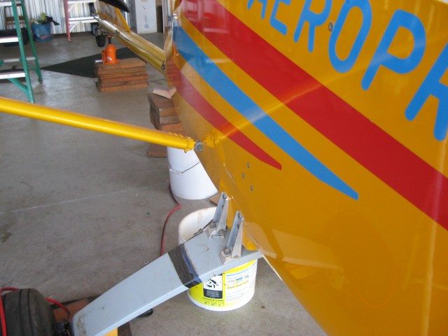
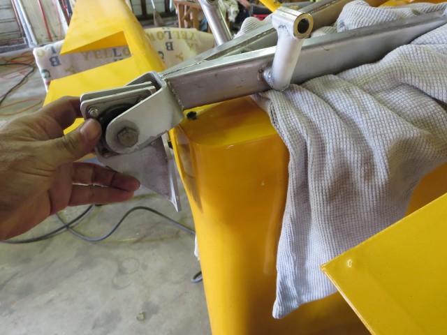
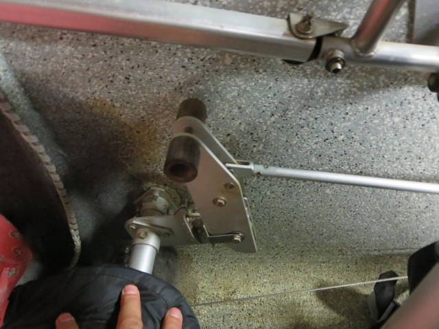
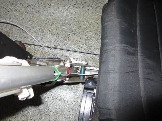
Remounting the gear
This turned out to be surprisingly difficult, something I thought would be easy…
I wanted to use the original mounting holes and not drill any additional ones. These holes go through an aluminum plate that is glassed into the foam core fuselage. Because the landing gear probably has some of the highest point loadings of any parts on the plane, I did not want to add holes, or make the existing holes any bigger than they were.
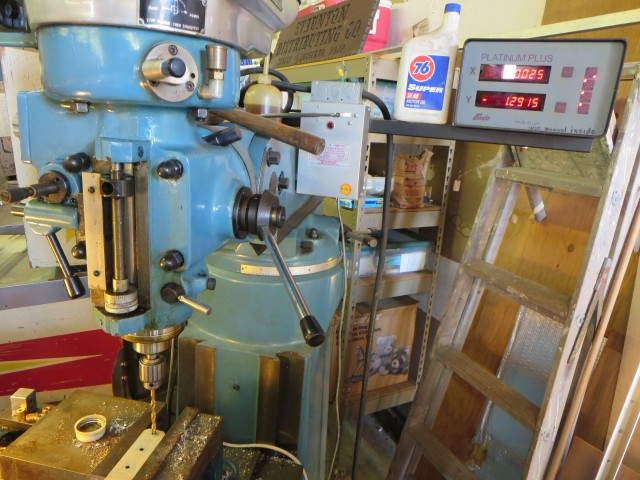
As you can see in the earlier pictures, the gear was mounted at an angle and the mounting holes as well. I measured the angle at 12 degrees and then used the digital readout on my mill to exactly measure the location of the holes in each of the mounting brackets. Each bracket was different. The existing holes had been measured and drilled by hand, easy to tell by the sloppy tolerances. The distance between holes was different on each bracket.
I had to do some trig and figure out how to re-cut and then drill each piece for the gear to end up exactly straight. Since the landing gear brackets and hardware were obviously hi tech materials and made from metric U channel to boot, I would have a very hard time making new ones. I really wanted to get it right the first time.
I made drawings and then reused the center hole on the rear brackets and drilled new holes top and bottom at the right distance and angle so they would be straight when remounted. I measured this over and over, and carefully set up the brackets on my mill. I used the degree scale on the large vice, and with the digital readout, I was able to get them exactly correct and the holes lined up perfectly, with a tight fit, when I remounted them.
This turned out to be very satisfying, as everything worked out as I planned to do it and the parts just mounted right up with the gear straight. I wish it was always that way.
Brakes
Because I had the gear off, and the brake lines had been taken apart, I had to re-bleed the braking system. I made the mistake of putting in Dot 3 brake fluid, when what is needed is either aircraft silicone brake fluid, or Dot 5 which is pretty much the same thing. These are Matco wheels and brakes. When I realized my mistake, I went to Matco’s internet site, and they said that if I did this, the brake system was ruined and the master and wheel cyls would have to be rebuilt. Bummer.
I talked with a friend and he told me that it took weeks for the damage to occur, and if I just flushed the system with the right stuff, and then bled it out as normal, it would be fine. I did as he said, and the brakes are fine.
Removing the Rotax 582’s
This was pretty straight forward, but consumed a week of my time. I sold the first engine to a friend, and the second one to a gentleman in Georgia. It was about a days work each to remove the engines, and two days to crate the one to be sent off on motor freight.
All the lines, fuel, controls went through the trailing edge of the wing and were not easy to remove.
I got a pallet and built a mount for the engine on it, and then built a box around it. Shipped it off and the plane was now ready to move forward.
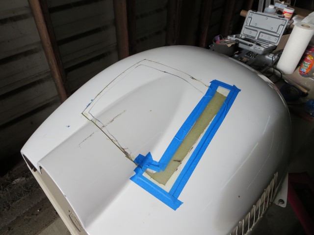
Fixing the Ailerons
The twin engines protruded through the ailerons. The ailerons continued inboard of the engines. The new cowling was wider than the old center fill piece, so the inside edge of each aileron needed to be moved out and the gap where the motor was, filled in. There were also gaps in the upper wing surface, which we will get to shortly.
The small dilemma with this was whether to try and just fill in the fabric, or rip all the fabric off. I opted to keep the fabric on the outer portion and just put new fabric on the modified part. Turned out that removing paint on the fabric, so that new fabric could be added and joined was a huge problem. In retrospect it probably would have been easier to just rip all the fabric off and recover the whole thing.
Cowling repair
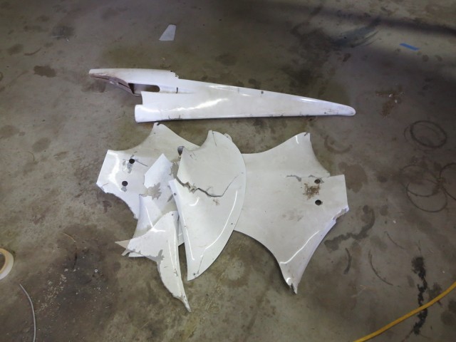
The cowl from the crashed A20 along with the rest of the airframe had been acquired by someone else. I was able to acquire the cowl, along with the fairings that went over the tailwheel, and the landing gear to fuse joint. All these pieces had to be repaired. The engine cowl had a big piece cut out of the top. Fortunately most of the piece was still there.
The lower half of the cowling had a big crack and had to be rebuilt also. I didn’t get any pictures of that one, although you can see the edge of the crack in the trial fit picture of the cowling further down.
I haven’t repaired the other fairing pieces yet. Here’s a picture of them.
Unfortunately, I forgot to take pictures of installing the Dzus fasteners to hold the cowl on the plane. I had never done this before. It’s a fairly straightforward process, a hole is cut in the wing top and a spring mounted on the back side. Access to the holes near the trailing edge was tough. There was an access cover to get to the throttle cables and what not that ran through the trailing edge, and it got me about 8″ from the Dzus fastener holes.
Interesting factoid, Dzus fasteners were invented by a Ukrainian who had emigrated to the US.
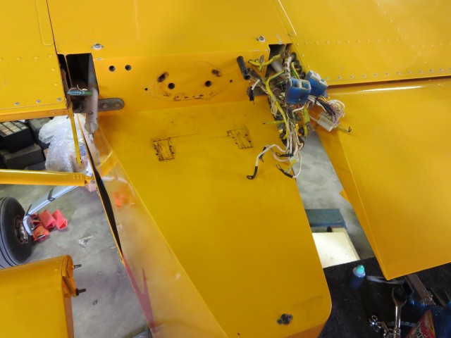
Filling in the wing gaps
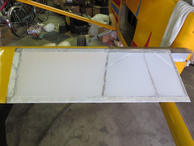
In the picture below, you can see the gaps left in the upper wing surface, where the twin engines were removed.
I cut two pieces to size, out of the large aluminum piece that covered up the electrics and wiring at the back of the fuse pod. The paint was a perfect match (the same paint). I also found some poly enamel at a hobby shop that exactly matched so that I could paint the edges of the cut pieces. Blends in pretty good.
And here are the ailerons and wing gaps all filled in.
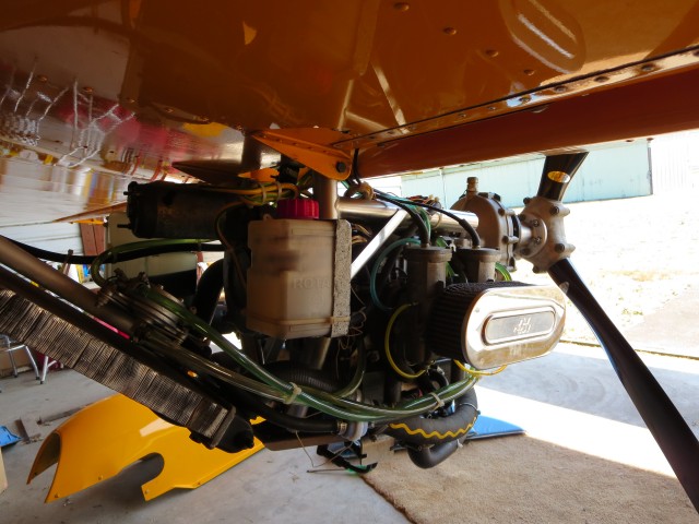
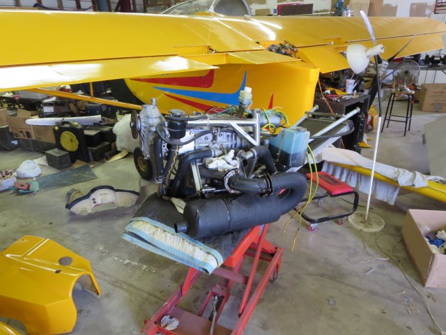
Mounting the new engine
Actually it wasn’t new. The Rotax 912 was from the crashed A20, having first been sold in 2001. It had 276 hours on it and had been lovingly maintained by the previous owner. When I bought the motor, the EIS came with it, and it was already set up for this engine. This was to be the hardest part of the conversion, as there was no instructions, nothing to copy, I was in totally new territory.
The installation would be similar to what is on the A20, but significantly different. Though they look the same, the A26 had significant differences in detail on this section of the plane. Fortunately, all the differences were to make this part of the plane stronger and beefier, to support the twin engines. All dimensions were different, varying from about 1/4″ to 3/4″. This meant that I couldn’t just copy the A20 installation. Even the motor mount had to be cut up and welded back together to fit.
Because of the thicker bullkhead, the motor was going to end up about 3/4″ more to the rear than on the A20. This could only be good, as my preliminary calculations indicated I was going to possibly have a too far forward CG.
With the mount right, several trial fits were done with motor. All in all, the motor was mounted on the plane 4 times before the final installation. I have a cherry picker, a device for installing engines in cars and trucks (a small crane, really), and this tool made it relatively easy to do.
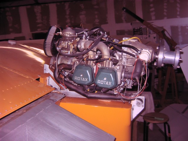
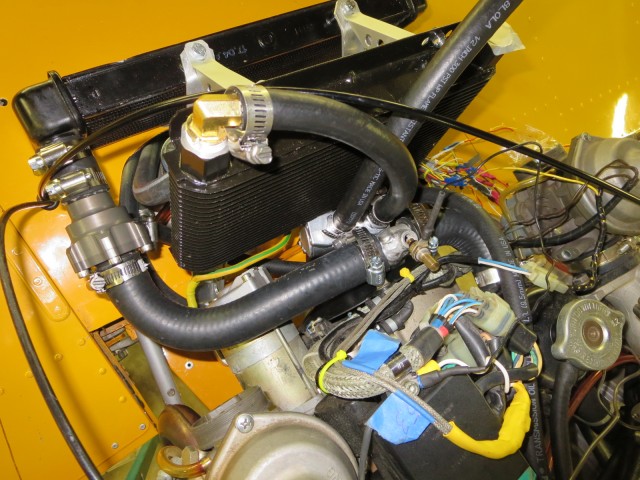
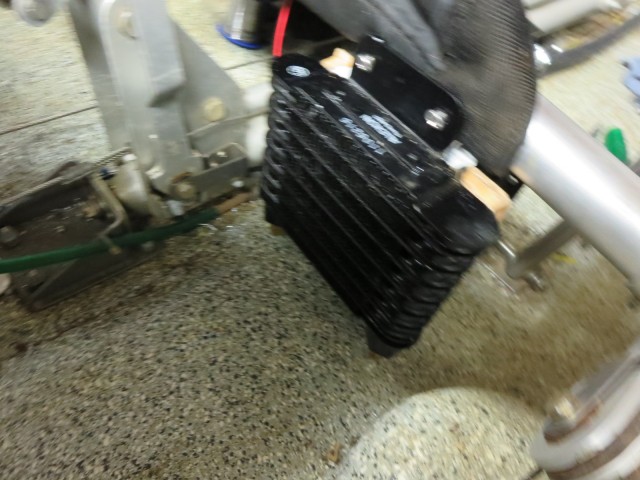
The major pieces to be mounted on the plane were the oil tank (the 912 is a dry sump engine), the radiator and the oil cooler. Once the cowl was on and the plane and marked, and some basic measurements taken, I first mounted the oil tank bracket and then worked on the radiator and oil cooler.
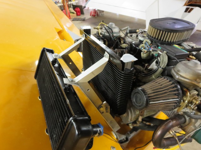
It seemed the standard install of the Rotax oil cooler on the A20, on all the planes or pictures I have seen, is mounted with the hose barbs down. This meant there would always be air in the oil cooler, drastically reducing cooling capacity. The oil cooler is not under pressure, it is on the supply side of the oil pump, and the pump sucks oil through it from the oil tank. In order to turn the cooler over, I needed right angle hose barbs, and the only metric ones I could find that would fit the Rotax cooler, were from Rotax, at $69 each. I bought a new race car oil cooler with SAE fittings, and right angle SAE hose barbs for it were $5 each.

Once I had the brackets done, I put them in the vice on the mill and cut in the lightening holes you see. Everybody that looks at the installation comments on these holes and how nice they look. Really this was very little effort or skill. With my digital read out mill, this took about 15 minutes. The rest of making these brackets and getting the radiator and oil cooler to fit took about 20 hours to get right. But no one comments on that!! LOL
I added a thermostat for the radiator, and one for the oil cooler also. The oil cooler is the top one. A big problem with oil coolers and engines in the winter is the oil not getting warm enough. The thermostats also facilitate a quick warm up when the motor is started, particularly when the weather is cold. Also, the motor will retain its heat when idled in flight, for example when I am soaring, which I plan to do with this plane a lot.
It’s pointless to go into all the details of hooking up everything for the engine. Anyone who has ever done this knows what’s involved, especially for a motor change to different type. Almost 200 hours total on the motor installation alone.
The most frustrating part of this was obtaining 1″ radiator hose with bends in it. I spent over two weeks finding hoses that could be adapted. Finally, I found out that NAPA auto parts has a big book with all manufactured radiator hoses in it, arranged by hose size. They were able to get me two hoses that I cut up and made work.
Throttle cabling
I was surprised to learn that the 912 carbs were set up by Rotax so that they are spring loaded to pull the carbs OPEN, or to full throttle. The cable pulls them closed. I’m sure lawyers had a hand in this, the idea being that if a throttle cable broke, you wouldn’t lose power, but go to full throttle instead. Supposed to be safer. I know that on most certified GA planes there is a single carb and a push pull throttle, with a spring on the carb to pull it open in case the cable breaks. That’s where the idea came from.
Well, the very nice throttle controls on this plane were set up for 582’s which have spring loaded closing carbs. A little searching on the internet found two examples of where this odd carb setup on the 912 has caused TWO crashes. One of them on the ground and another crash while landing. In both instances no one was hurt but the planes were totaled. I couldn’t find a single instance where the setup had prevented an accident. So, I opted to change them back to the way the carbs were designed. All the hardware is there, on the carbs, to do it. These same carbs, by the way, are on the HKS engine. I previously had an HKS on my Odyssey experimental, so I am quite familiar with the setup.
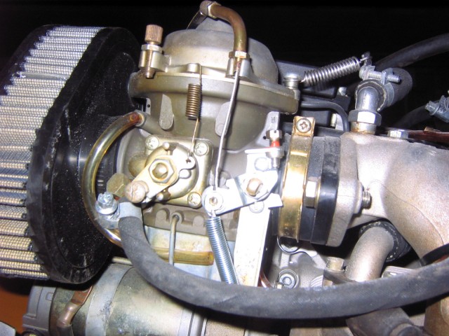
Once this is done, idle, balancing and everything else is much easier to set. The throttle stop screws allow a good idle to be established, that doesn’t depend on the throttle mechanism. Any airplane newsgroup where the 912 engine is used has many, many posts about this problem. Not too many people convert back to the way the carb was designed.
The rest of the installation can only be described as normal for a motor installation from scratch. Anyone who has done a motor replacement, ie. installed a different motor than stock or different than the plane was designed for, can appreciate the time and seemingly endless fit and refit of every component involved.
An additional part of the motor installation, was the heater, which I installed up under the pilot seat. Two hoses run back to the coolant lines of the motor, and there is a small fan on the heater.
According to the Rotax 912 installation manual, getting the air out of the oil system so that the pump can function properly can be a real problem when setting up a new engine installation. They recommend pressurizing the oil tank and turning the prop by hand, 60 or more revolutions or until oil pressure comes up on the gauges.
I bypassed all that by filling the oil tank through the oil cooler and the oil line going from the cooler, through the thermostat to the motor. This was the highest point in the system. This way the oil cooler and lines were full of oil. It was very slow going, taking almost 10 minutes to feed 3 quarts into the system. But, the system was saturated with oil, and just a couple prop revolutions by hand brought up oil pressure on the EIS. On first startup, I had instant oil pressure that did not waiver.
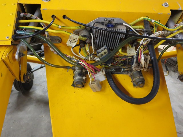
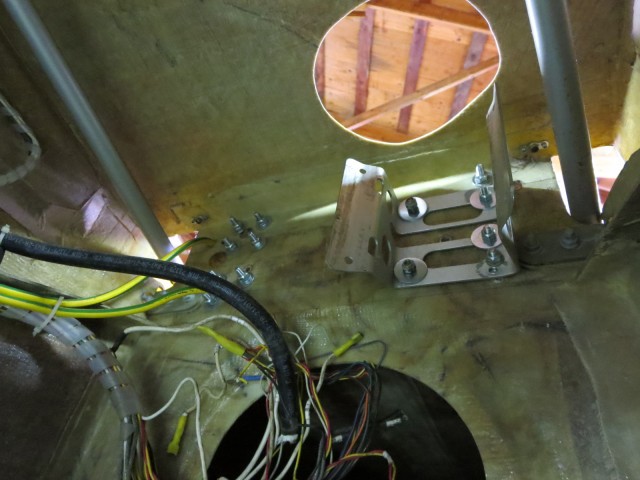
Wiring
The existing wiring in the plane turned out to be a disaster. I thought that I could just make some basic changes, and easily be able to wire in just one motor where two had been before. There was a wiring diagram from Aeroprakt and it appeared like that was what was in the plane. But… it had been modified. A video game controller stick handle had been wired into the plane and mounted on the pilots control stick. (I kid you not) It had several push buttons and they were wired to control the Nav lights, the strobes, and the landing light, and maybe even the radio, through added relays behind the panel.

At some point, also, an attempt was made to mount a car stereo and have it play into the headset system. The comm radio that came with it was non op, and this may be how it was damaged.
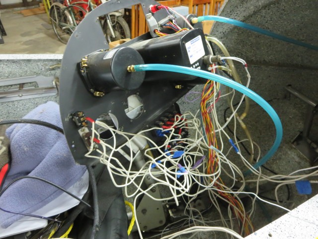
I decided to give up on the installed wiring and start over. I just disconnected everything and identified and labeled all the wires at both ends with a battery and meter, and then rewired everything, using the old in place wires where I could. This actually worked out ok, as there were many extra wires from the two engines. The EIS wiring was in a harness supplied by them, so it was pretty much workable. I just had to make couple changes, right at the multiconnector that plugs into the EIS.
As far as the pilots control stick, since the top of it had been cut off when the game controller was added, I had to find a piece of tubing that was an exact fit over the old tubing and then cut to fit. I put a nice PTT switch on the top of the stick.
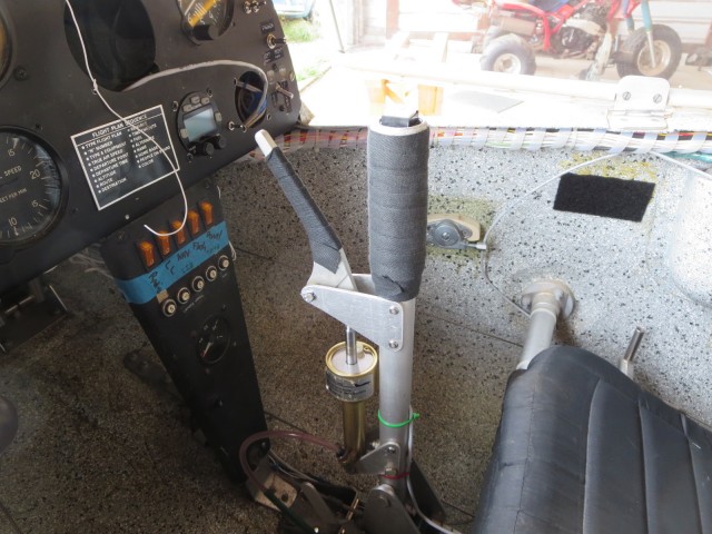
Additionally, I added a bungee chord to the elevator rod. It exactly balances out the weight of the elevator and the elevator does not fall, but stays neutral when sitting static. The bungee will need to be changed each year at annual time, and will be noted on the list of things to do.
At this point another radio, an Xcom 760 was wired in and works ok. Only ok because the antenna needs radials or a metal sheet added to the underside of the fuse top where it is mounted. Since the fuse is fiberglass, it does not provide a ground plane. When this is done, the range will probably at least double.
Weight and balance
This worried me more than anything else about this conversion. Removing two rear mounted engines and replacing it with one slightly heavier engine mounted at a different arm point, well… I didn’t know where the CG was going to be. The existing pilot’s manual had minimal info about CG, only minimum and maximum weights for the pilot and passenger. There was no computational data such as zero datum point, or arm length distances to either seat or the fuel tank.
I knew that I had to just do it from scratch. With the help of a friend, we used string and a plum bob, cleaned the floor off really well beneath the plane, and got it up at flying attitude on 3 electronic scales that I and a few friends own. We then put tape on the floor and marked all the pertinent points so we could measure them with a tape measure on the floor.
Since the wings have 3 degrees of sweepback, we marked the leading edge at the mid-point of each wing, and pulled a draw string between the two points, marking the point under the plane, giving us the average leading edge due to the sweepback.
I computed the CG with the plane empty, and then with a friend in the pilot’s seat. Using his known weight and some math, we were able to derive an arm length for that seat. Then we measured to what would be the same point on the rear seat.
Turned out that some tail weight had to be added for me to fly the plane. With my weight the CG is close to the front of its range. I don’t like to fly with the CG like that. I made up an 11 pound weight from lead shot and epoxy, to mount at the back of the tube. It is removable and safety wired. The passenger weight is just a little ahead of the CG. The plane is significantly lighter than it was in twin engine configuration, 675 lb empty. With a gross of 1126 lb, that gives a comfortable useful load.
The CG actually worked out pretty well. I don’t like adding weight, but it is what it is. Here are the specs on the weight and balance, etc. I figure this info might help out some other A26 owner, or even someone else wanting to do the same conversion.
Empty weight of plane with oil and coolant, no gas is 675 lb. With lead weight added to tail boom 686 lb.
Zero datum– fuselage nose
Main gear datum–73″
Average leading edge datum –80.25″
Tailwheel datum– 238.5″
Pilot datum– 42.5″
Passenger datum– 74.5″
Fuel tank datum– 99″
Wing chord — 55″
CG range, 17-39% of chord — 90.25″ – 102.25″
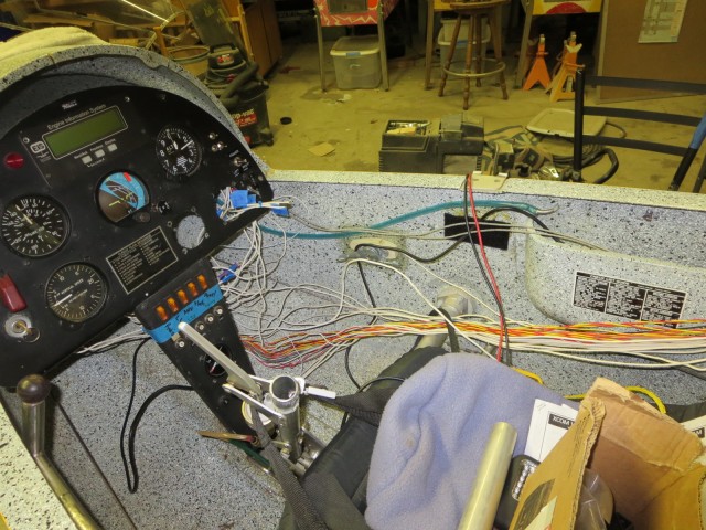
Panel Instruments
When I acquired the plane, the attitude gyro was not operational, it whined but would not hold position at all. The Microair radio would not power up. The Microair transponder would power up, but I was not sure of it’s functionality.
I figured that all of these instruments could have been damaged in the A26 from the bad wiring. The EIS would consistently indicate low voltage, 9-11 volts when the battery was fully charged, which could have caused damage to all three instruments. Consistently low voltage will do that.
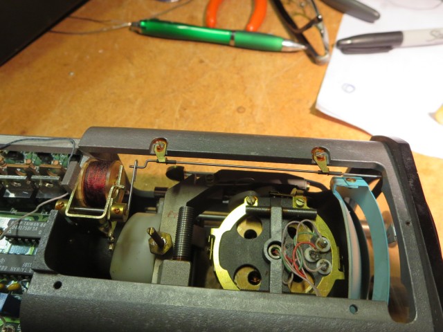
I have a small business with my sons, where we repair vintage ham radio gear, and vintage stereo equipment. This means I have a complete two way radio test bench. I can test radios, and even transponders, but we really can’t work on them. The subminiature construction of modern avionics uses surface mount technology, and we are not set up to repair this kind of equipment.
However, I gave the gyro a try. I disassembled it. The electronic drive circuitry (old tech, not surface mount) for the rotor/motor seemed to be OK. Dis-assembly and re-assembly of the rotor was a major job, taking a couple hours, but was straight forward. I cleaned and lubed the rotor assembly; cleaned the bearings out with degreaser spray; and added a couple drops of synthetic oil to each. When power was applied again, the rotor spun up, and it seems to be working ok now.
But, I think the gyro was installed improperly to begin with. It is marked as a zero degree gyro, which mean the panel it is mounted on should be vertical in level flight. The panel in this plane has about a 16 degree panel tilt in level flight, and so the gyro would continuously be out of spec. If you “Pull to Cage” on this gyro in this panel, the rotor will not be vertical and the gyro will not function correctly. I will either have to build out a vertical mount for it on the panel, or get a different one, or not use it at all. I’d like to have one of the new 3.3″ miniature EFIS modules, that just came out. They weigh only 5 ounces and would add a definite safety factor to this plane.
I will have the Microair units repaired at their US repair station. They have surface mount components throughout, and as I said, not repairable on my bench. A friend with an experimental LSA has spoken for them and will install them in his plane when they come back.
When I acquired the Rotax 912 from the crashed A20, I also made a deal for the owner’s Xcom radio, and Becker transponder, both supposedly in good working condition. The radio is in and working. I fabricated a wiring harness for it, and installed the music input option. The transponder seems to be ok, and will output considerable power when checked on my test bench with the Ident button.
Conversion — A26 to A20?
Actually, this is not a complete conversion. This plane will really be a hybrid, that is neither an A26 or an A20. Maybe an A21? I expected it to end up weighing more, but it weighs almost exactly the same as a regular, 33′ wing A20. The differences are in the lack of wing tanks, and because of that, lack of luggage capacity (storage space) in the fuselage. Aside from some very minor differences in dimension, the outward appearance will be almost identical to an A20. When completely painted, only the tail, rear seat throttle controls and larger, wheels and wheel pants will give it away.
If I happen to get to know a builder with the requisite skills, who is willing to help out, I might consider trying to add wing tanks to this plane. Then a smaller tank could be used in the fuselage. It would be nice to have more luggage space. All in all, though, I am very happy with the plane as is.
Update 12/9/13
The plane has been flown a little over 8 hours. Started with 12 crow hops that would balloon up to 50′ or more. Off the ground in 300′ or so at about half throttle. Luckily we have a 4000′ runway, so getting back down was no problem. No stall testing done yet, but based on landing settling speeds it seems the stall speed is less than 35mph with just the pilot on board and less than 10 gal of gas.
This plane has excellent directional stability, seemingly flys like it’s on rails, but still responds quickly to control input. It seems to be the easiest landing tail dragger ever made. All landings have been wheel landings and every single one near perfect. The gear works well and there is almost no bounce. The fiberglass gear seems to be just as advertised, dampening as well as adding spring action.
The fuel burn is looking great. Flying around the patch, staying very close to the airport, at low speeds, 60-80mph has produced a fuel burn of about 1.75 gph. We’re still calibrating the flow function on the EIS, but this seems to be correct based on fuel burned so far.
So, as far as achieving the goal of reduced fuel burn, I think the project has succeeded in spades. At these “low n slow” speeds, it would seem the new plane burns less than 1/3rd the fuel of its earlier incarnation.
And the heater? 20 degrees F outside and nice and toasty in the cockpit.
Registration problems
Ab0ut 5 days after the plane passed Airworthiness Inspection, I got a call from the DAR, saying there was a problem, the FAA had questions about the 51% checklist I had filled out. The plane was grounded and I had to provided explanations as well as another 51% checklist.
The problem as I see it, is that the Checklist was written so as to ask questions about a kitbuilt aircraft or a plane being built from plans. Not an unusual project such as this. I’m pretty sure someone at the FAA reviews this checklist and uses it for oversite on the kit built registration process.
I just filled it out, without much thought, marking lots of items as non-applicable, and that was my mistake. Looking at it from the point of view of oversite, my checklist did not give a big picture or tell the story of what had happened with this plane. The second time, I added many items in the blank spaces provided, a one paragraph summary of the complete conversion process, and explanations of each item on the checklist done by the builder(s).
I think this might be a pretty unique project. I wonder how many kit built twins have been converted to a single engine configuration?
They re-instated my Airworthiness Cert. We’re all happy and smiley here, again. A valuable lesson learned.