


Secret Stuff
Some of this is repetitive, but is worth reading through. I’ve done a lot of posting on some audio forums and I’ve just included some of the best posts.
From Audiokarma post March 2009—Secret stuff
OK, here it is. This is what you do to bring up a 9001 to best performance. I was going to add my capacitor list also, but when I looked at it, I’m 70 some capacitors short, so the final version of my list must not have gotten saved in the excel program. Anyway, here it is. I got a bunch of emails from my bay ad, all wanting to know this stuff. Enjoy and take your time doing these mods.
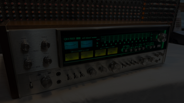
These are the things you do to restore and upgrade a QRX 8001/9001
Replace all the electrolytic caps
Replace the fusable resistors with normal metal film resistors.
Fix and resolder the pass through solder joints on the double sided pc board
Remove the 3 blend resistors on the quad processing boards
Do the “Holy Grail” quad alignment
Re align the tuner
Set the amplifier offset and bias to factory spec
Here is all the “secret” data on updating and restoring the QRX 9001
The Holy Grail alignment
The 3 blend resistors, that decrease separation in the quad processing boards, are:
On F2087
R39 100K (on my 9001, this was 39K)
R40 100K
On F2088
R601 220K
Remove them for more separation.
After they have been removed, you must realign the quad outputs with the 4 potentiometers on the F2088 board
First you must set the voltage for the quad boards at 25v. This is very critical and must be done carefully, with the boards in circuit and the unit on. You do not want the voltage to go too high, or too low while you are adjusting it, or the quad processing IC’s can be fried. I think the limits are 36 and 18 volts, so you should easily be able to stay in that range. The pot is on the little power supply board behind the tone control (bass and treble) boards. You can either measure the 25v at the little power supply board, pin 1, or at the plug in connector for F2088, pin 5. Do this carefully and set for exactly 25v.
Next, set the four pots. You need some kind of audio generator that will generate 2 channels of 1 khz tone. They will either be in phase (mono) or 180 degrees out of phase.
You can use the VU meters on the 8001/9001 to measure levels.
The Fusable Resistors
These are on the amplifier board, F2624. They are a different color than the other resistors, kind of a flat light blue. They should be replaced with same value, ½ watt metal film resistors. Use metal film cause they can take the extra heat.
R35, 36, 47, 48, 49, 50 = 4.7 ohm
R39, 40 = 10 ohm
R41, 42, 43, 44 = 150 ohm
R33, 34 = 180 ohm
Adding Polypropylene Caps
If you wish to add poly caps to the signal path electrolytics, you can do so by adding .047uf polypropylenes in parallel with the electrolytics. You have to look at the schematic and mark all the signal path caps on each board. I’m sorry, but you have to know enough to mark these and then find them on the boards. A good hint is that the signal path caps are practically all the electrolytics between .47 and 4.7 uf. Larger caps than this are often power supply related. There are a couple exceptions, but you can find them by reading the schematic.
Some people may argue that the electrolytics should be completely replaced. I won’t go into theory too much about this, but if the poly cap you add is at least 1/100th the value of the electrolytic, you will achieve the same thing. The most expensive audio devices made in the world, mixing consoles that cost over $1 million, use this technique. It is indistinguishable from completely replacing the electrolytic with a poly.
AudioKarma post from April 2009– More on Holy Grail alignment
Hi all,
I have been playing with the quad processor pot adjustiments on my 9001 (which is now gone, by the way. Now I just have a 7001 and a 6001 to play with) and have some additional findings and thoughts about it. I have updated the original posting. Also I changed the 25v adjustment point from pin 5 of the F2088 plug in board to pin 1 on the little power supply board, behind the tone control boards a better point for measuring. Pin 1 is the second pin down on the right side of the board. Pin 5 on the 2088 connector is easier to get to on the 7001 and 6001.
Here’s the addendum on the alignment, from the beginning. The new stuff starts at “Explanation for . . . . ”
Explanation for Adjustment steps 1 and 2 below
Low in volume but equal, means this: Since you actually can control the “equal” part with the front/rear balance control, what you should really do is the following. As you move VR4 from one extreme to the other you will at some point see one of the two right level meters dip before the other. You want to split the difference and have them both as close to the dip point as possible. It will almost seem like there are two positions of VR4 that will do this. Which one do you want to be on? This is real important–
Put on a pair of headphones and plug them into the front headphone jack (turn the 1 khz tone off first), still in QS mode. Listen to some source that has good stereo separation. While listening turn VR4 through its range. You will notice the stereo separation collapses down to almost mono. So, one end of the pot will have good separation, the other end will have less. For the HG alignment # 1 and 2 below you want to pick the dip point on the pot towards the rotation that gives more separation not less.
I set mine so as to maintain as much separation on the front channels as possible and yet still very close to the dip point. You may even want to play with this a bit and pick a dip point that sounds best to you, actually listening to music through the speakers (headphones, too) and then going back to the 1khz tone adjustment. I found that this makes a big difference to the airiness of the reverberant field when listening to stereo sources in QS mode. Whatever you do here, though, make sure that VR3 and VR4 are adjusted the same.
I think the point here is that if the music is recorded with a “coherent” reverberant field, the Sansui QS can do wonders with it. Coherent would mean all the instruments playing into and subject to the exact same reverberation. When recording that would mean the entire piece is mixed down to one stereo pair and then that pair run through a reverb source that is added back into the mix. That reverb source can either be electronic or the natural sound of a venue.
When live, that “coherent” reverb source is the reverberation that is in the venue. It is recorded along with the rest of the performance with microphones that are aimed at the space and not at the performers. It could be as few as 2 or as many as 10-12 mics, all mixed down to a stereo pair themselves, that is added into the main mix. The point of this is that all instruments play into this reverb space and are subject to exactly the same multiple reflections.
Sometimes though, even when recording live, electronic reverb and other effects are added to the natural reverb of the hall. With pop music, this is, more often than not, the case. Classical is practically always recorded with just the sound of the hall. A very popular way to record classical is with the “Decca Tree” , so called mic setup. (google if you’re interested”) Many engineers will use the Decca Tree, but also add some additional hall mics into the mix if needed.
So, I have found the QS to sometimes be stunning in its sound field creation with live recordings of classical, jazz, and other performances that do not have added electronic reverberation. And this is where the adjusting VR4 and VR3 towards more front separation can make a big difference.
Pop music that has lots of different reverb fields, as well as all kinds of other electronic effects, will be dealt with by the QS processor in lots of different ways, with lots of different outcomes. Sometimes, truly delightful, sometimes just weird. I think all of the above is why.
This may all be the reason that the blend resistors were there to begin with. Maybe the Sansui engineers found that, without the blending, it was possible to adjust the pots so as to cause the processing to collapse the front stereo image down to almost a mono sound. I think that removing the blend resistors, setting VR1 and VR2 for most separation, and setting VR3 and VR4 for most pleasing effect, is the way to go. The setting of VR3 and VR4 may vary with room and speaker placement.
I’d really love to hear what some of you other quad tweekers out there think of this. To me, adjusting the processor this way has increased the quality of the effect by 2-3 times. There is now some music, when played through QS, that I would literally swear is DVD A or SACD and not just QS processed stereo.
Adjustment
1. First, play a LEFT only 1khz tone into the Sansui in QS mode and adjust VR4 until the output on the RIGHT front and back channels are low, but equal. The Right Front and Back channels are always out of phase with each other. When they are equal in volume, that is known as “strict imbalance”.
2. Now, play the RIGHT only 1khz tone. Adjust VR3 so that the LEFT front and back channels are low and equal.
3. Now play the mono tone (equal in both channels and in phase) into the Sansui. Adjust VR2 so that the REAR channels are low and equal in level.
4. And finally, play a 1khz tone to both left and right channels that is 180 degrees out of phase into the receiver. Adjust VR1 until the FRONT channels are low and equal in power.
That’s it! You will be amazed at the difference. This is from Tab Patterson’s web site, 4channelsound.com